Flow: 5-800m3/h
Head scope: 12-60m
Outlet Diameter: 25-300mm
Priming height: 4.5-6.0m
Medium temperature: ≤100℃; Medium viscosity<100cp, Solid content less than30%, medium heavy does not exceed1240kg/m3
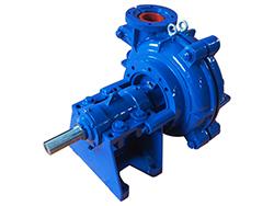
Product Overview
The ZX/ZW self-priming centrifugal pump is designed according to ISO international standards.
Our pumps are manufactured using a ceramic ring mechanical seal to prevent liquid with particulates from entering the sealing surface and damaging the pump. This ensures the stability of the pump during use. There is no need to install the bottom valve in the pipeline. It is only needed to maintain a quantity of priming liquid.Therefore, it simplifies the pipeline system and improves working conditions.
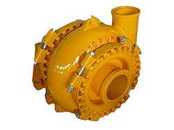
Self Primer Pump Application
The ZX/ZW Self priming slurry pump is primarily designed for municipal environmental protection, construction, fire control, chemical, pharmaceutical, printing and dyeing, brewing, electric power, papermaking, petroleum, mining and other industries. It is used to transport clean water, seawater, chemical medium liquid with acidity or alkalinity and slurries.
This self priming slurry pumps can be used in conjunction with any type and size of filter press, and it is the most ideal pump to transport slurry to filter press for filtering.
| Model | Inlet (mm) | Flow (m3/h) | Head (m) | Power (Kw) | Speed (rpm) | Priming Height (m) |
| 50 | 3.2 | 20 | 1.1 | 2900 | 6.5 | |
| 32 | 3.2 | 32 | 1.5 | 2900 | 6.5 | |
| 40 | 6.3 | 50 | 4 | 2900 | 6.5 | |
| 50 | 12.5 | 50 | 5.5 | 2900 | 6.5 | |
| 65 | 25 | 70 | 15 | 2900 | 6 | |
| 80 | 60 | 70 | 22 | 2900 | 6 | |
| 100 | 100 | 65 | 30 | 2900 | 6 | |
| 150 | 170 | 55 | 45 | 2900 | 5 | |
| 200 | 400 | 32 | 55 | 2900 | 5 | |
| 250 | 550 | 32 | 75 | 1450 | 5 | |
| 300 | 500 | 50 | 110 | 1450 | 5 |
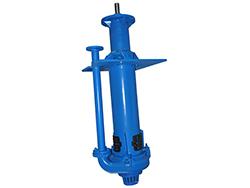
Pump compositions
ZX/ZW Self priming slurry pumps adopt an axial return liquid pump structure. The pump body consists of a suction chamber, liquid storage chamber, scroll chamber, liquid return hole, gas-liquid separation chamber, etc.

| Part Description | Material Specification |
| Coupling | Cast Iron |
| Shaft | Stainless Steel* |
| Bearing | Cast Steel |
| Mechanical Seal | Cast Iron |
| Bearing Assembly | Cast Iron |
| Pump Casing | Cast Iron |
| Outlet | Cast Iron |
| Inlet | Cast Iron |
| Front Seal Ring | Cast Iron |
| Impeller | Cast Iron |
| Rear Cover | Cast Iron |
| Beffle Ring | Cast Iron |
| Liquid Filling Hole | Cast Iron |
| Liquid Back Hole | Cast Iron |
| Bolts | Zinc Plated Steel |
Other shaft material options are available.
Drive art: electric motor, diesel engine.
Seal form: Mechanical seal.
Product Features
1. Good self-priming performance: The suction height is 1 meter higher than the conventional self-priming pump, and the self-suction time is minimized.
2. High efficiency and energy saving: The efficiency is 3~5% higher than that of the conventional self-priming pump.
3. Strong sewage discharge capacity: Special anti-clogging design of the impeller ensures high efficiency and prevents clogs.
4. Convenient operation: It is easy to use, move, install and repair.
Precautions for pump maintenance
After the pump runs for a long time, when the rolling bearings, the front and back sealing rings wear to a certain extent, they must be replaced. Mechanical seal should not be opened for inspection in case of no leakage. If there is serious leakage in the leakage hole below the bearing body, users should dismantle the mechanical seal for inspection. When you dismantle the mechanical seal, you must handle with care and pay attention to the cleaning of the fitting surface. Besides, you should protect the mirror surface of the static ring and moving ring and keep no knock. The repair method for leakage due to mechanical seal: you can grind the end face to restore its mirror effect; if the O ring is broken, you need to replace the O ring for reassembly.
Pump disassembly sequence
A. Remove the electric motor or disengage the coupling.
B. Remove bearing assembly, check the radial clearance between impeller and front mouth ring, check if the impeller nut is loose.
C. Remove the impeller nut, pull out the impeller and check the radial clearance between the impeller and the back sealing ring.
D. Loosen the set screws of mechanical seal, pull out the dynamic ring part of the mechanical seal, check the fitting condition of the end face of the dynamic and static ring, and check the sealing condition of the O sealing ring.
E. Unscrew the set screw of the coupling and pull out the coupling.
F. Remove the bearing cover, pump shaft and bearing.
G. The assembly can be done in reverse order during installation.